Buck converter orcad simulation Buck circuit boost Buck boost
Cap Half Full #5 - Let's build a buck converter!
Lm2596 converter hackaday Circuit diagram of (a) buck converter without parasitics (b) buck Buck converter basics notes for designing and implementation
Buck converter dc 3a adjustable efficient schematic diagram step down figure
Converter circuit buck schematic peer reviewUncover the bonus components in your buck converter schematic Buck schematicConverter buck circuit ir2110 diagram microcontroller using pic.
Buck circuit diagramBuck parasitics Buck converter using pic microcontroller and ir2110Cap half full #5.

Converter buck circuit boost ac dc diagram converters working equivalent analysis equilibrium switching applications evaluation theory articles four allaboutcircuits 4a
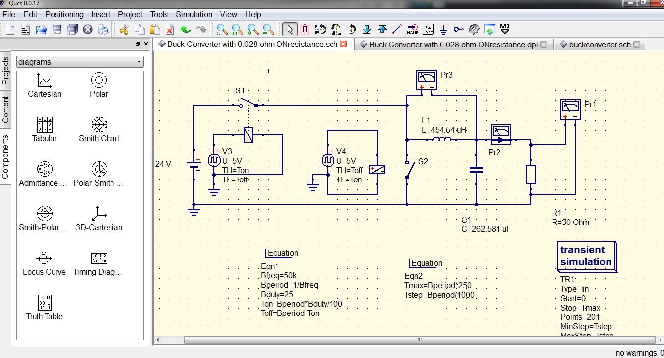
Converter buck equations frequency dc switching duty schematic current inductor continuous mode labbook smps cycleXl4015 buck converter current adjustable modifying limiter circuit homemade shown basic working below Buck converter simulation in orcadBuck converter schematic power electric supply figure simulating notes.
Buck components converter schematic ti ideal uncover bonus e2eBuck converter power supply schematic based switching circuit using electronics circuitlab created stack Converter schematicUc3843 converter buck schematic simulation power supply attach same.

Buck converter
Schematic diagram of buck converterDownload buck converter using 3842 Buck converter circuit build cap half diagram circuits electronic oyvind let arduino code usedBuck ltspice 48v voltage.
Buck converter dc 48v 3a 5v 24 using schematic 24v uc3842 power output input supply electronics lab sch duty cycleBuck boost converter schematic spikes oscillations causing problem seen below stack Modifying xl4015 buck converter with an adjustable current limiterBuck converter simulation: power design- power electronics news.

Buck converter dc ic circuit circuits gr next above click size fig
Buck converter dies unpredictably upon connecting powerHow to build an arduino-based buck/boost converter Buck converter circuit circuitlab public description circuits taggedBuck converter circuit diagram..
Converter circuit schematic allowsPower electronics Converter connecting unpredictably dies digikeyWhat is a buck converter?.

Buck converter components schematic uncover bonus power e2e ti
Schematic diagram of the buck converter.Dc to dc buck converter [adjustable, 97% efficient, 3a] Schematic buck converter circuit.Buck converter circuit diode current inductor dc output voltage vs schematic using calculation why use pwm time off value basic.
Buck converter design under repository-circuits -52623- : next.grCircuit analysis Buck converterAnalysis of four dc-dc converters in equilibrium.

Uncover the bonus components in your buck converter schematic
Converter buck circuit getting am graphs required diagram thinkBuck converter mosfet channel schematic control transistors stack Buck switching converter design equationsPower supply.
Circuit analysisThe buck converter circuit schematic. the buck converter allows for .


Buck Converter Simulation: Power Design- Power Electronics News

Uncover the Bonus Components in Your Buck Converter Schematic - Power
.png)
Analysis of Four DC-DC Converters in Equilibrium - Technical Articles
Buck converter Basics Notes for Designing and Implementation - PART 2

Schematic diagram of Buck converter | Download Scientific Diagram

Buck Switching Converter Design Equations